We continue the tutorial by analyzing the tracks.bin file
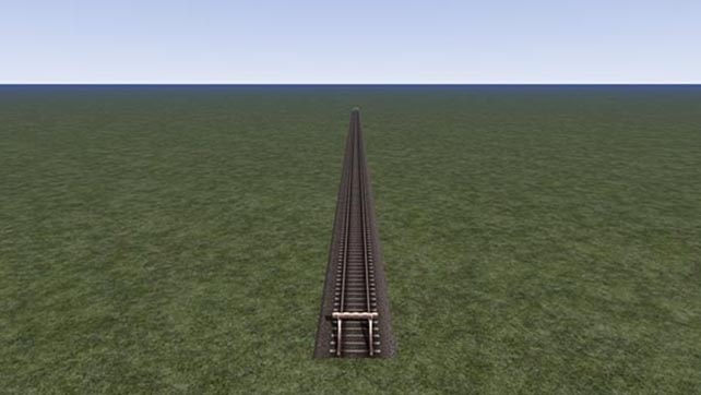
To analyze the basic structure, we start from a single-track route that is exactly 500m long and perfectly straight.
I make a small premise that applies to the whole tutorial. RW creates macro tags that have only one child that could seem useless, but that obviously serve to RW maybe for a quick search in-game or for reasons not clear to me. To understand what I mean, I collapse some of these levels.
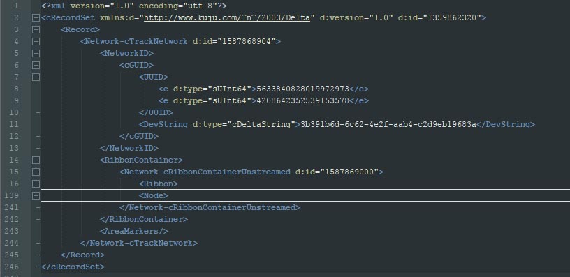
In the end we see that all the content is within the Network-cTrackNetwork construct. I made this premise because situations of this type are also found within other part of the file and when this happens, I will analyze only the tags that are of interest, not those that seem to be only container, so consider it if you do not see mention to some tag.
Let’s continue. After saving and analyzing the tracks.bin file, you can notice the basic structures, which are the same for any route, but whose individual elements will then be complicated depending on the content.
The first part of content starts with a NetworkID tag, which contains unique IDs for the entire track plan. The DevString tag appears here for the first time. Again this is a unique GUID that defines a specific data / object. This specific case for the tutorial is not interesting, but we will see that every object in RW, including scenery objects, lofts, and in this tutorial the tracks, have a DevString that uniquely identifies it.
Then the section that interests us begins. What we need to focus on is the part inside the Network-CRibbonContainerUnstreamed tag. All our track plan lies within this opening and closing tag.
This portion is divided into two macro constructs (in the image they are collapsed):
Ribbon. Inside there are all the tracks with their definition of length, positioning, altitude, type of track, etc, which we will see shortly
Node. It contains all the nodes of the tracks, that is to say the beginning-end of each laid section, possible junctions with other tracks, etc.
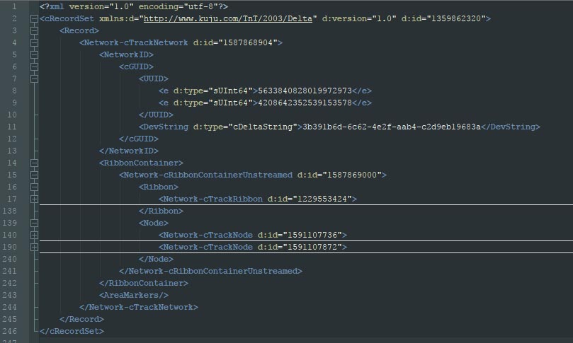
Having laid only one track, I therefore expect to see 1 element under Ribbon (1 track) and 2 elements under Node (start and end).
By expanding the Ribbon and the Node to a lower level, I actually get what is expected (line 17 – 140 – 190):
Each of the new entries is also identified by an ID as a tag attribute. This ID is used in some way by RW, but we do not have to rely heavily on it, because every saving operation of the tracks.bin this ID is generated from scratch, so it is not fixed at all.
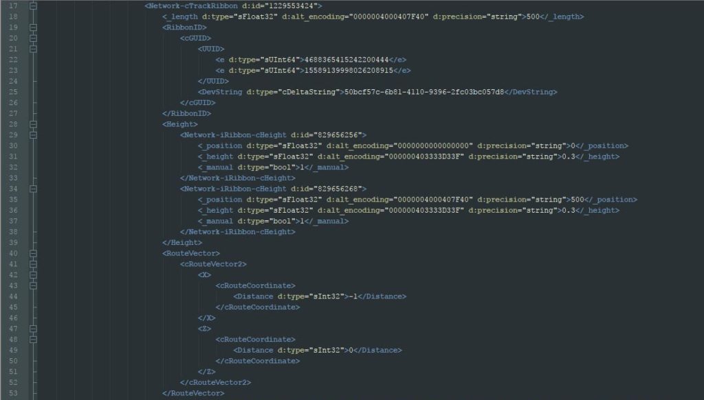
Next step is to analyze the Network-cTrackRibbon. Although the track is simple and without add-on such as signals, milepost or junctions, the number of lines is not so small. Let’s start with the first part:
The first tag is clear, defines the length of the section of track we have laid, which I remember to be straight, of exactly 500m.
The second tag is the unique name of this section of track within RW and therefore within all the files of our route. The unique name is as mentioned previously in the DevString tag.
We then move on to the definition of heights. Preamble is that the single-track route is at height 0 and the track itself has any height variation (flat).
Therefore, within the height tag there are two pairs of values related to the two ends . The linear distance of the beginning of the track (0) and its relative height (0,3m), and the linear distance of the end of the track (500m) and its relative height (0,3m). The value 0.3 instead of zero is because the track is raised 30cm by constructive definition of the track itself.
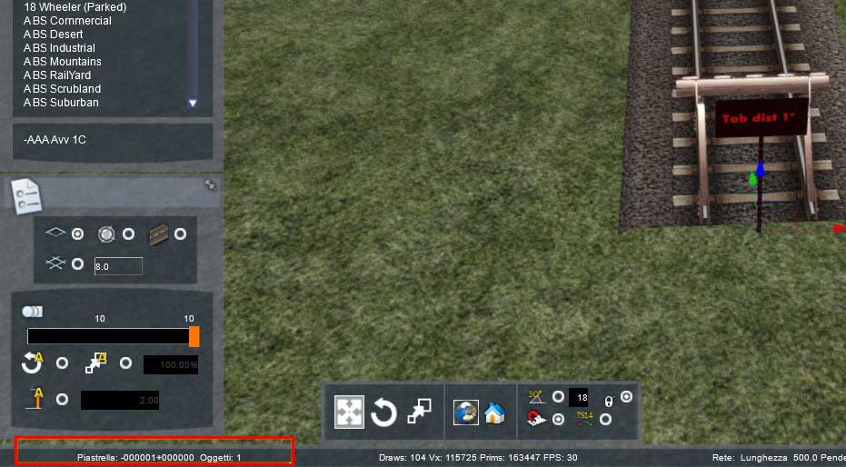
The next tag is the RouteVector, which specifies the tile to which the track has been assigned. The tile is obviously one if the track is completely inside it. If the track (as in the case of the example) crosses two tiles, the game engine must define one, which is usually the one from which the track is started to be laid on. In this case the tile is -000001 + 000000 and in the image below you can read that tile number on the bottom left (red box) is correct.
Now there are two constructs that define start and end, in terms of positioning, within the tile (or of the tiles if the track is between two). It is correct that there is this construct because so far we know that the start and end point have a certain height, we know which tile is affected, but we do not know where and how it should be positioned inside the tile.
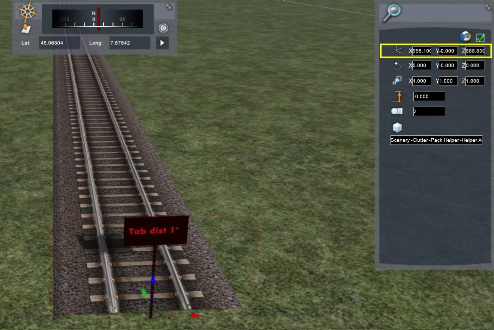
The first node RBottomLeft defines X and Z (Y in RW is considered height) of the starting point. To confirm it in the screenshot below I placed a sign exactly at the beginning of the track and in the yellow box that represents the positioning of the sign (but also the starting point of the track), we see that both the X and the Z are, unless approximations in the editor, identical to what is reported in the file.
PARTICULAR NOTE: in some rare cases it may happen that the coordinate seems different, and normally happens when the object placed for verification (in this case the sign) has negative coordinates given by RW. Actually when this happens, just make the complement to 1024 (which I remember to be the width of the tile) of the object coordinate and you get the correct number again. For example, the first time I put the sign, RW gave in X the value -28.9. If I make a difference
1024-28.9 = 995.1 I again find what is saved in the file.
The next RExtents node is the relative position in X and Z of the ending node with respect to the starting point. In this case I have laid a straight track parallel to the X direction and then the first value is 0 (I do not move right or left with respect to the RW grid). The second, being a perfectly straight track, is exactly the same as the length, so 500 (apart from obviously minor errors of 5th order which are however kept in mind). In short, the point of arrival is aligned with the starting point (X = 0) and 500m over (Z = 500).
The last two nodes are not clear to me, in the sense that they are always the same. I assume they are nodes for the management of the route editing phase. In any case, I have never seen different values.
In summary, what we have seen so far defines the main points for the management of the track section. However, it does not define any of its properties, for example which track rule I used, what speed I set, signals, curvatures, different heights, etc …
This is maintained by the next section, defined as a whole under the Property tag that is located within the Network-cPropertyContainer tag.
The Property tag can be small or very long depending on the properties that are to be applied to this section of track. Obviously in our simple case, we are just at the minimum; we have no signals, we have only one track rule, we have no speed variation, the track is of only one type, etc …
Within the Property tag in our simple case there must therefore be a minimum subset of sections.
PARTICULAR NOTE. The order of these sections varies saving after saving, so I will list the sections but do not expect to always find them in that order.
Let’s start. One of the sections is the one to register the speed limits of the track section:
It is important to note that this section is created by RW if and only if at least one of the two limits is different from the default one of the applied trackrule. In this case I set the primary 130km/h instead of the default of 120 km/h.
The structure is clear, since the speed limits are the same for the whole track. The section then tells us that from the origin (0m) to the end (500m) the primary speed is 130 and the secondary speed of 100.
Let’s see immediately what happens (even if it is becoming intuitive) if I change the track and at a certain point change the primary limit to 110 km/h.
As expected, this section is split into two parts. The first is only modified by replacing at 500 the value in which the speed of 130 km/h now ends, in this case 347.713m. The rest of course does not change.
The second “new” section (which as mentioned is not necessarily immediately after the one above) is therefore created with an equivalent structure.
As was already clear, however, the start point becomes 347.713m, the ending point remains 500m, and the primary speed has fallen to 110km/h. From this small example we understand well how the tracks.bin file manages a certain property of the track (in this case the property is the speed), and how it records the changes of this property along the track itself. We will see this type of strategy again in other cases and for other properties.
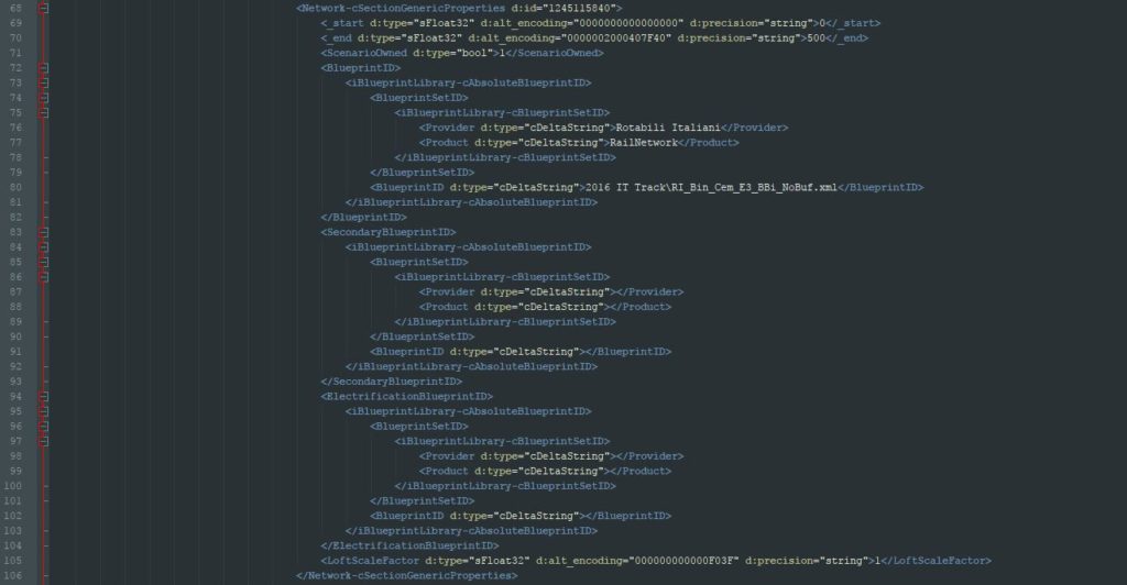
The second section always present even in simple cases is the one included in the Network-cSectionGenericProperties tag and which defines the graphic representation of the track:
At this point it is clear how to proceed. In this case, my track is of only one type (Concrete average status, white tracks and without final buffer whose model is called RI_Bin_Cem_E3_BBi_NoBuf).
Again start and end are clear, being a track of only one type, it starts from 0 and ends at 500m.
It is then specified which is the Blueprint to be applied (under BlueprintID) in terms of provider, product and model name with full path.
Then follows a sub-section SecondaryBlueprintID, empty because to my knowledge it is never used for tracks definition.
Finally, a similar sub-section for the electrification template. Here, during the saving phase, the electrification blueprint (catenary, third rail, etc) is inserted by RW automatically (info’s required are obtained from the track-rule), but only when the track itself has catenary, third rail or fourth rail electrification attribute. In my case the track was of the third rail type without blueprint assigned in the trackrule to be able to insert a custom loft type catenary, and therefore remains empty.
With these subsections there are therefore all the graphic information to be able to render the track in game.
We have now understood that if there were two different tracks in the same section, the respective section would have been split with the same concept of the example on the speed previously done.
The last Property sub-section that is missing from the appeal is the trackrule to be applied to the track which, appropriately, is inside a tag called Network-cTrackNetworkTrackRule:
There is not much new to say here, except that once again having only one track rule, the section has the usual start 0 and end 500 and in the following lines the provider, product and blueprintID of the trackrule to be applied are indicated.
For our simple case, the properties are finished and remain a couple of constructs before finally closing the tag that defines the piece of track (remember being the Network-cTrackRibbon):
Before closing the Property tag, there is still a construct that for the experiences I have done should be a progressive number that identifies the changes made by the first placement of the track.
It is not so important, while the Explicit-cDirection and Superelevated tags are more important. It is quite intuitive that the first registers the allowed transit directions in that track (in this case either means both directions), while the second indicates whether or not there is an activated binary inclination flag (0 means not activated) .
Unlike other tags, these two apply to the entire track section and it is not possible to have these characteristics set differently within the same section of track.
At this point we have reached the end of the part of the Ribbon knot of our very simple track. In the next tutorial we will take a detour on the trackrule, which will put a little question on what has been done so far, and then analyze the Node and the file under the Track Tile folder.


